Concepts, Diagrams and Calculations
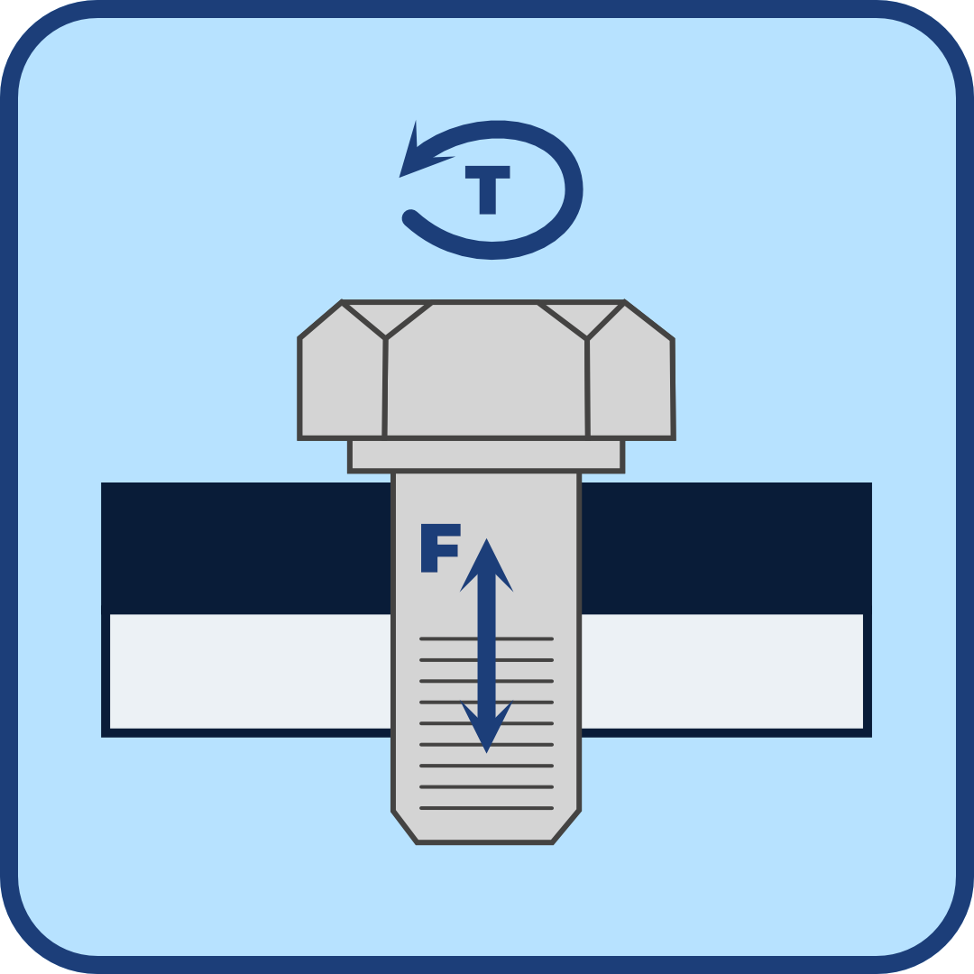
Fastener torque refers to the rotational force applied to a fastener (such as a bolt, nut, or screw) to tighten it. This torque ensures that the fastener holds two or more parts together securely without damaging the components or the fastener itself.
It is helpful to understand some fundamental concepts related to stress and strain prior to making any calculations or referencing torque tables in order to orient ourselves to a basic understanding of what torque is and what we are trying to accomplish by using it.
Below is a visual introduction to the diagram:
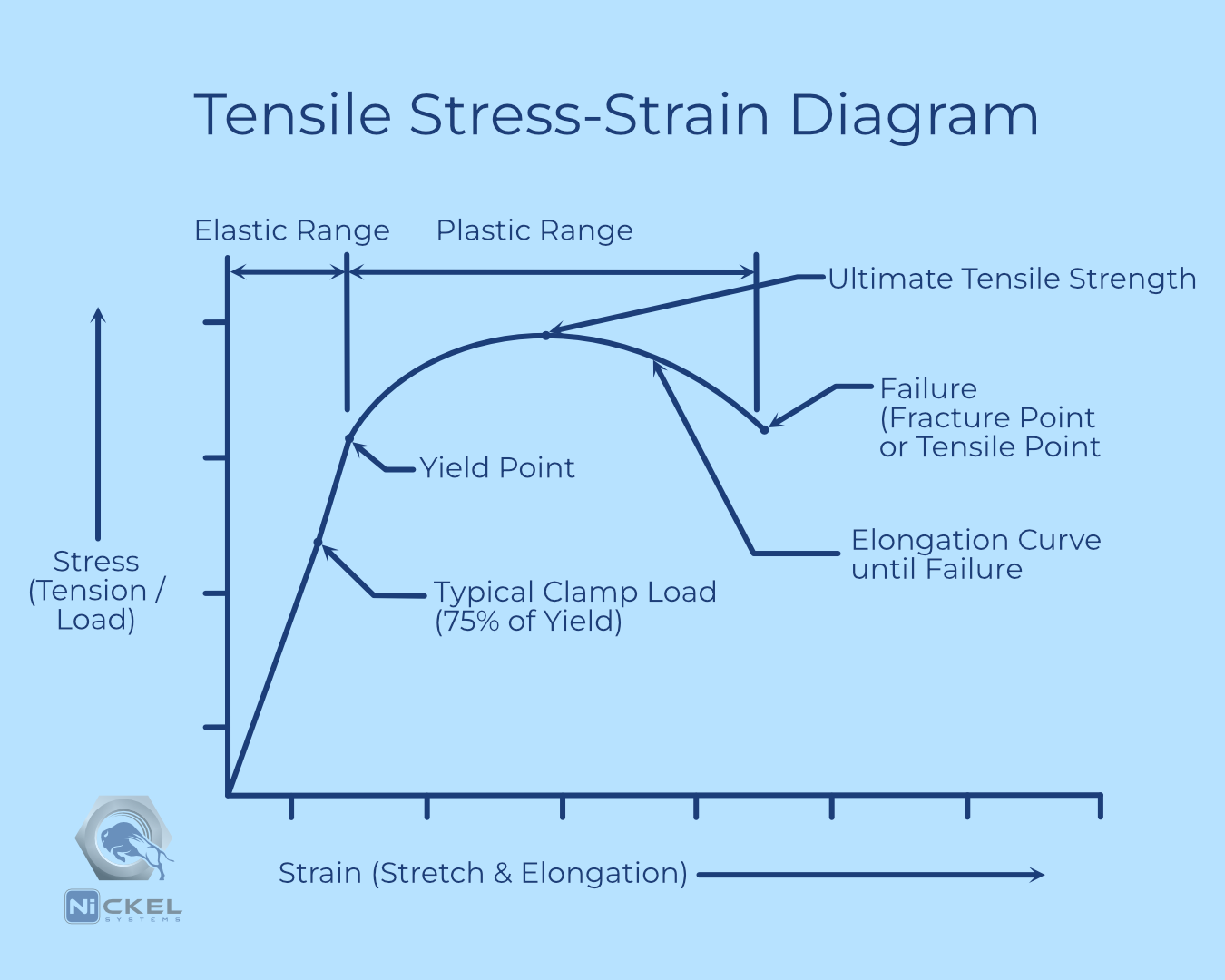
Stress refers to the internal resistance a material offers per unit area to an external force trying to deform it.
Formula: σ = F/A where:
Note: Pound-force (lbf) is a measure of force and is distinct from mass or weight.
Strain represents the geometric deformation of a material in response to applied stress. Essentially, it pictorially shows how materials behaves under loading.
Formula: ε = ∆L / Lο where:
Elongation Curve is a graphical representation of how a material stretches in response to applied stress. It includes both elastic and plastic deformation phases.
Elastic Range is the portion of a material’s stress-strain curve in which the material behave elastically meaning that it returns to its original shape when an applied load is removed. This represents reversible deformation.
Plastic Deformation is the permanent change in shape or size of a material when subjected to a stress beyond its elastic limit. Plastic deformation causes irreversible changes in the material’s structure.
Yield Point is the exact point at which material begins to deform plastically. This is often impossible to determine without testing. And even with testing, it changes slightly depending on test samples.
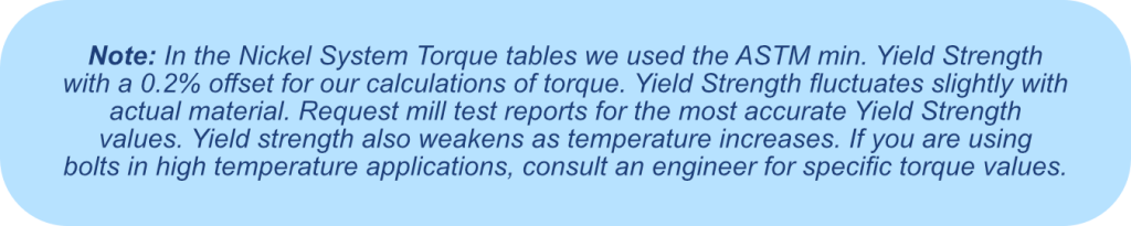
Yield Strength is the maximum stress level at which a material will begin to deform permanently.
Ultimate Tensile Strength refers to the maximum stress a material can withstand before breaking.
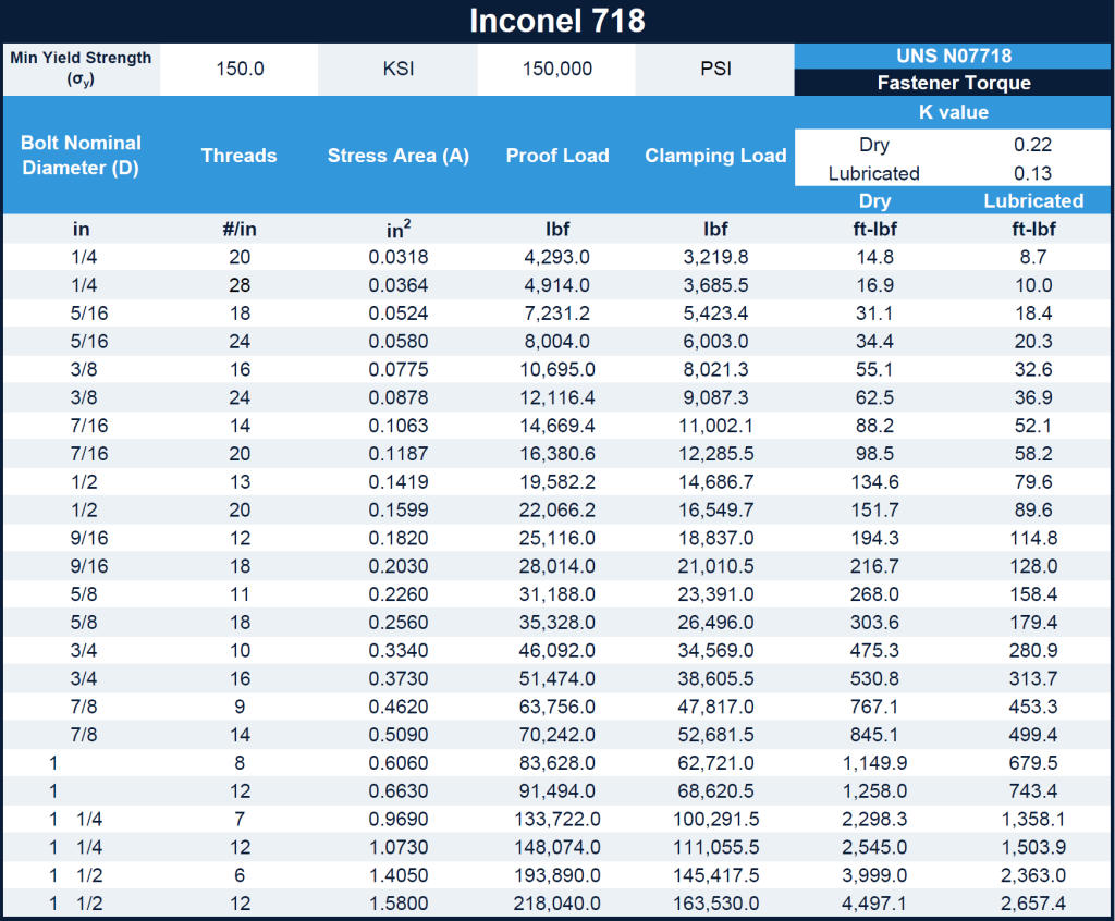
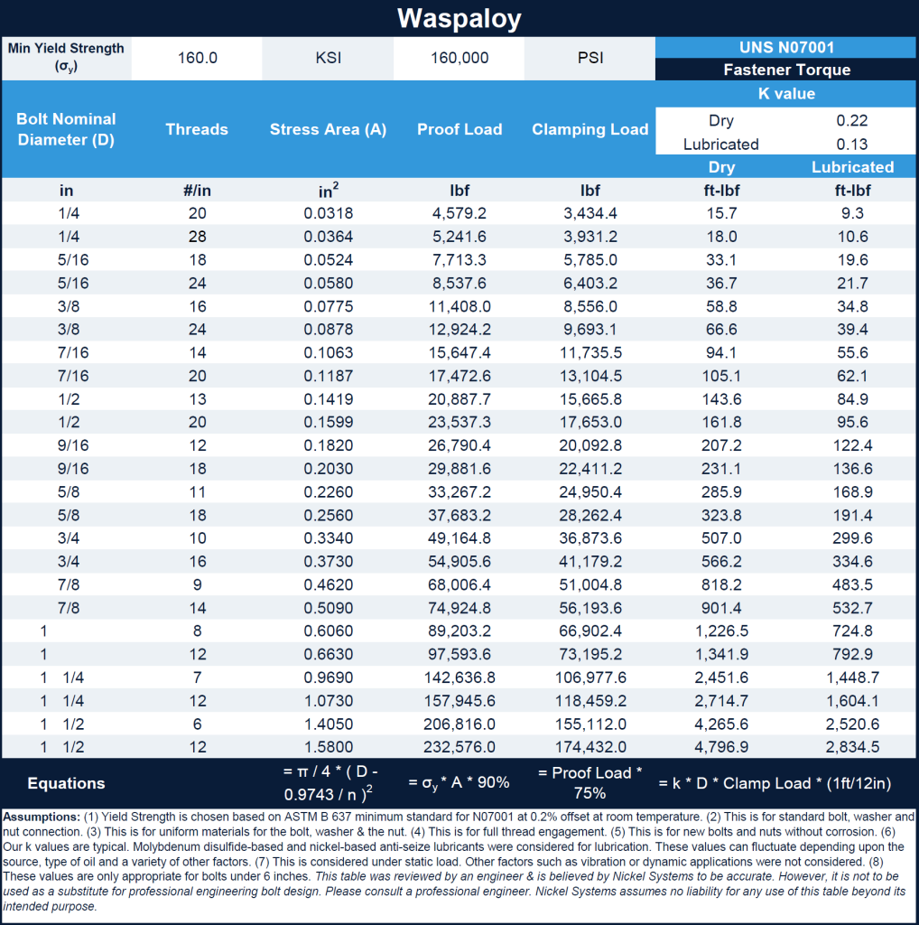
Proof Load is the maximum force a fastener can withstand without experiencing permanent deformation. Because the exact point fluctuates slightly, it is typical for the value to be multiplied by 92% to ensure that the yield point is not exceeded.
Proof Load = σy * A * 0.90 Where:
Clamp Load is the axial force applied to a fastener (i.e. bolt or screw) to hold components together in an assembly. Typically clamp load is multiplied by a factor of safety of 75% of the proof load. (This is a general factor of safety. Different industries and specific structural designs have different factor of safety values. Consult with a professional engineer for your specific application.)
Fastener torque is important because there needs to be enough load applied to the bolt and nut to prevent it from loosening. This can lead to a loss in structural integrity of the unit. However, too much fastener torque moving beyond the elastic range will lead to permanent deformation of the bolt and nut. This can lead to damage and failure of the structural components as well.
Here are the steps for calculating fastener torque:


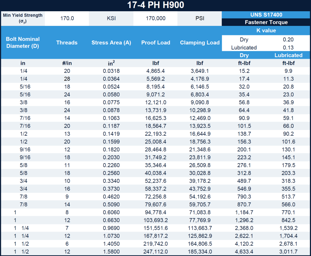
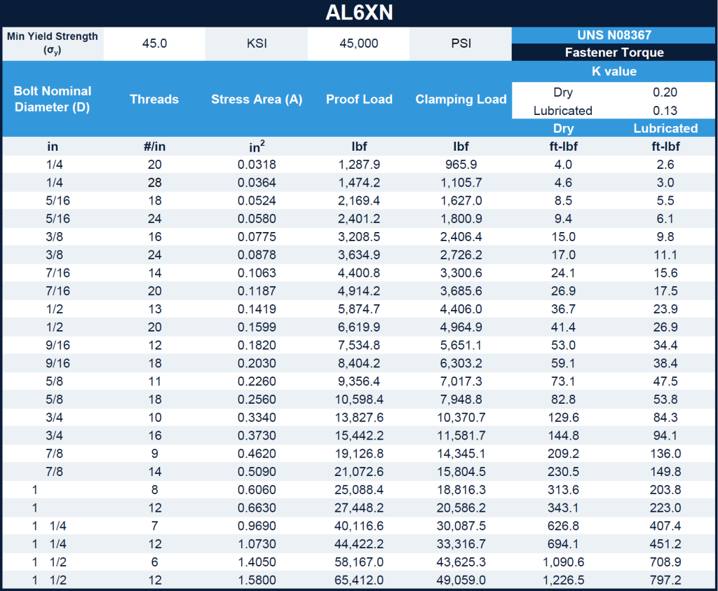
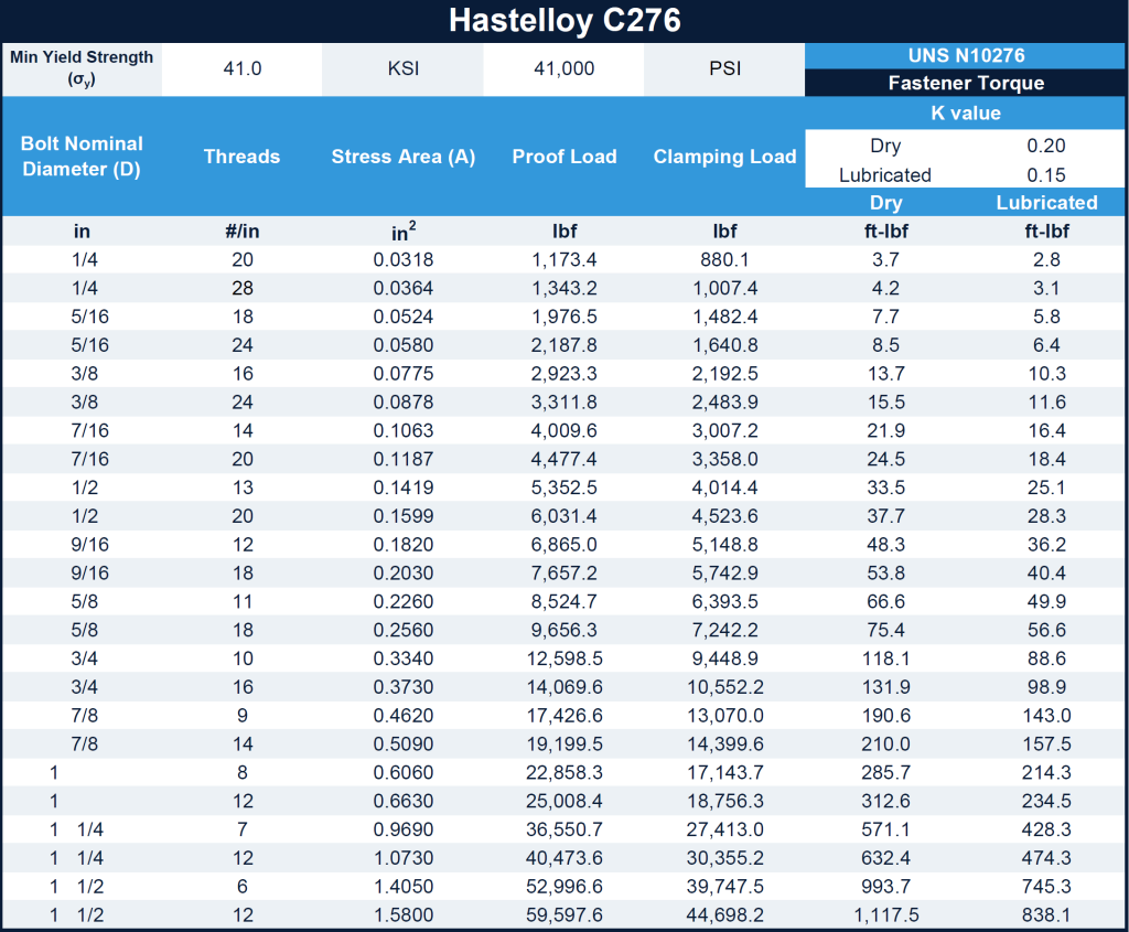
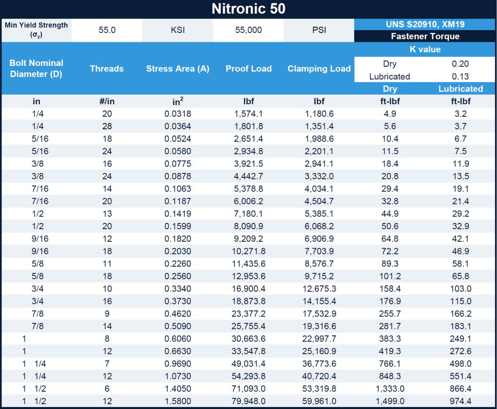
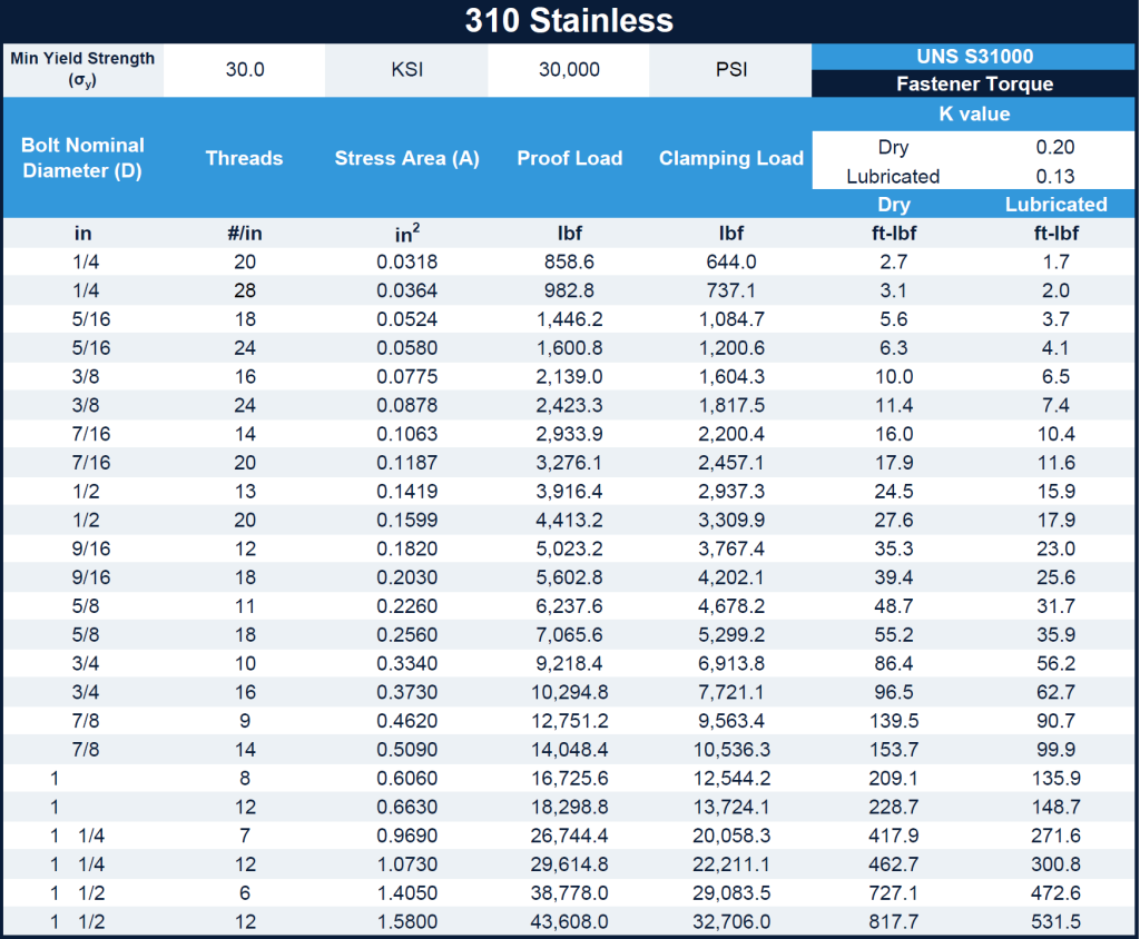
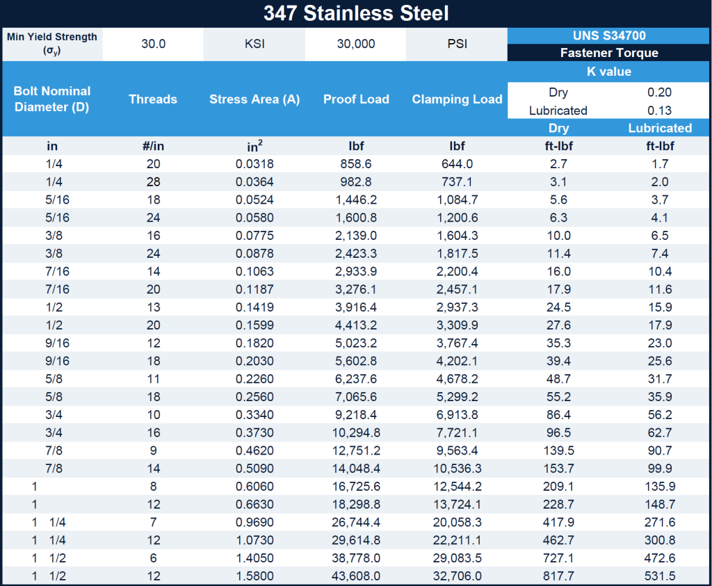
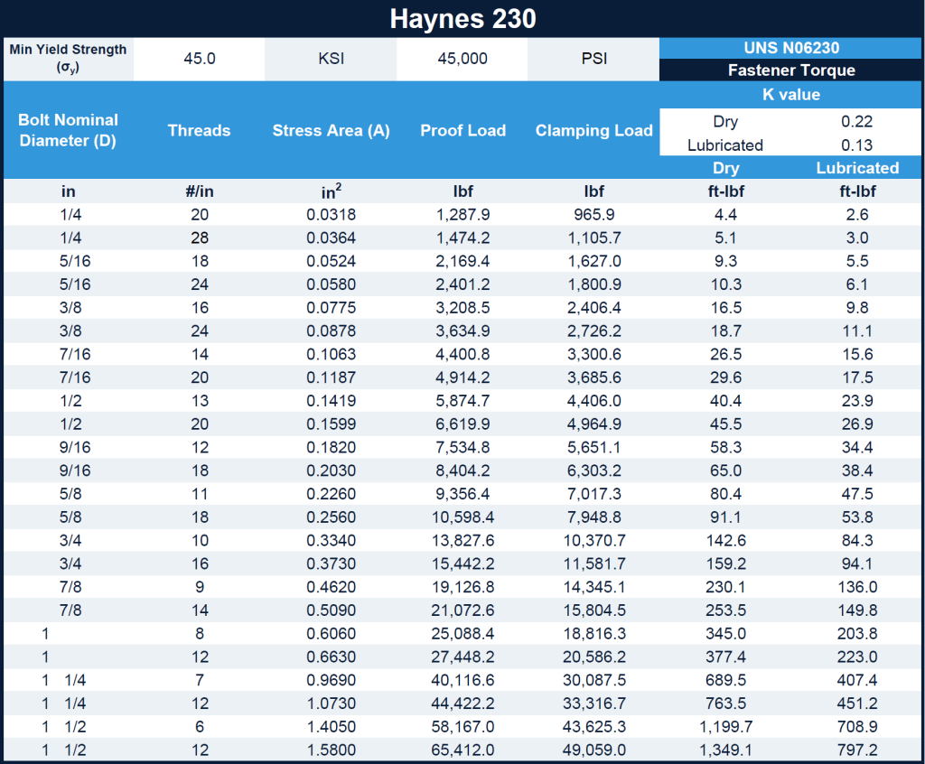
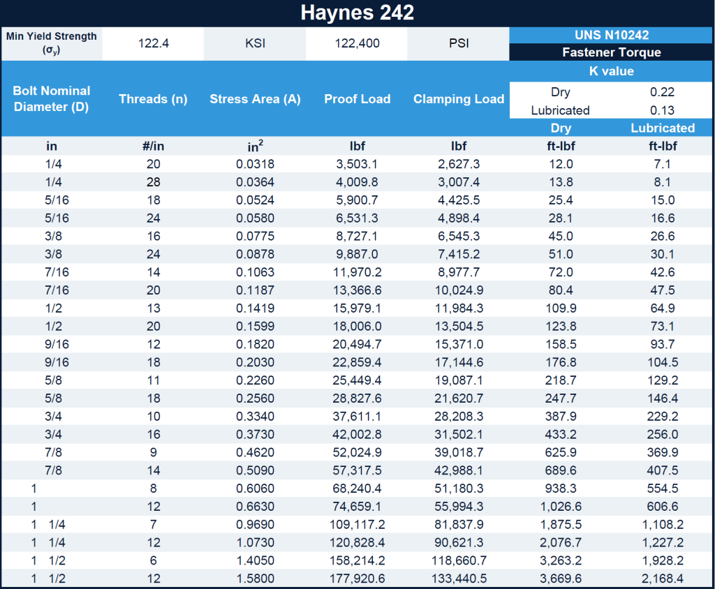
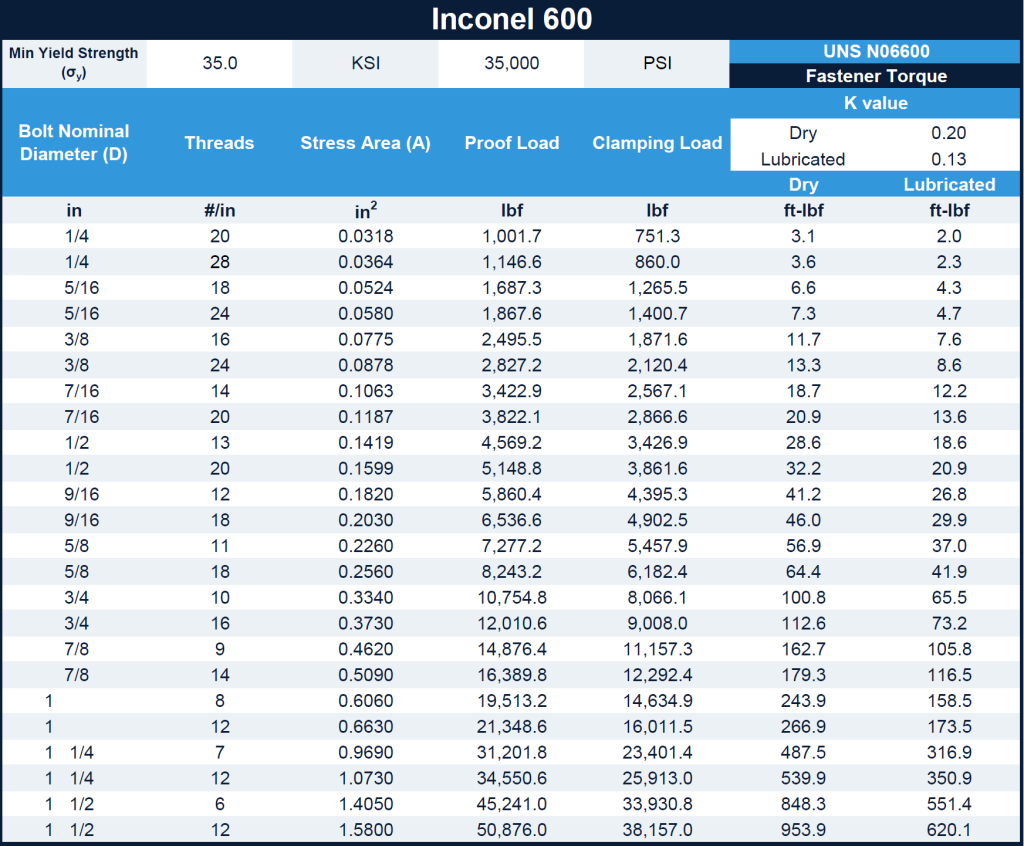
Get our torque tables. Click on the pics in the tabs below to get the full printable pdf!
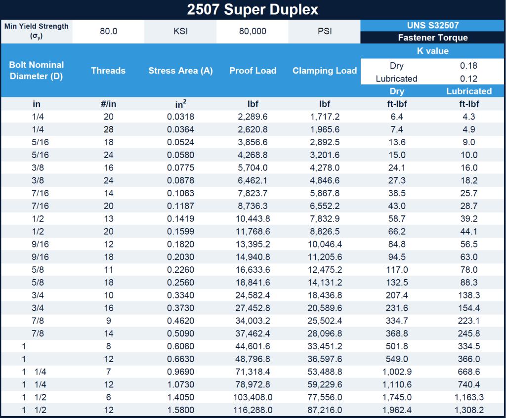
Get our torque tables. Click on the pics in the tabs below to get the full printable pdf!
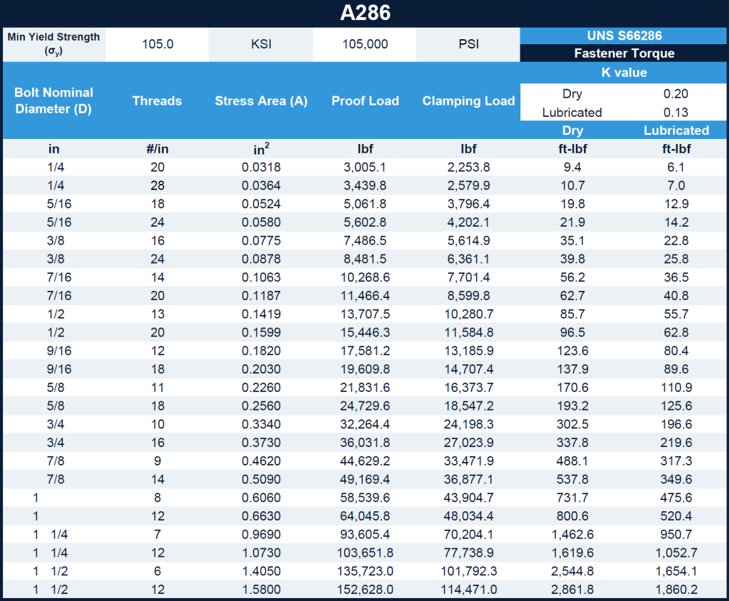
Get our torque tables. Click on the pics in the tabs below to get the full printable pdf!
Understanding and applying the correct fastener torque is crucial for mechanical assemblies. It requires knowledge of material behavior, stress-strain relationships, and standardized calculation methods. When executed properly, torque application ensures durable, safe, and efficient assemblies.
Reach out to Nickel Systems and begin your quote today for reliable, durable exotic alloy fasteners.
Request a Quote